

Some of you may have an Atari ST in your collection—but have you ever stopped to consider the condition of your floppy disk drive? There is a specific drive model that Atari installed in many ST units which contains cheap electrolytic capacitors. After all these years, these can leak and destroy the motor control circuit board in the process!
There is a remedy for this.
| feature | Value |
|---|---|
| Manufacturer | Epson |
| Designation | SMD-400 (sometimes also referred to as SMD480L) |
| capacity | 720 KB (Double Density) |
| Ttype | 3,5″ |
| Used in | including internally in the Atari 1040ST |
| Spare part number (Atari) | C103043-001 |
The problem: Leaking SMD electrolytic capacitors
This concerns the Epson SMD-400 drive. What I discovered here is something Amiga 500, 600, and 1200 owners know all too well from their own SMD electrolytic capacitors: the three small SMD capacitors had already begun to corrode the contacts. In a case like this, you should act quickly: remove the capacitors and replace them with standard leaded electrolytic capacitors. These are 10 µF capacitors—five of them in total—and they should be replaced as soon as possible!
Three electrolytic capacitors are visible at the front; the fourth is located at the far rear left, and the fifth at the rear right. To access them, the entire ejection mechanism must be disassembled.
Remove the old electrolytic capacitors and clean the contacts.
It is important to snap all five electrolytic capacitors off the circuit board by firmly twisting them in both directions, and then to treat the areas around the solder pads with Kontakt WL cleaner to neutralize any leaked electrolyte—this is a crucial step. Afterward, use a soldering iron to remove old solder residue from the pads and clean them thoroughly using desoldering braid.
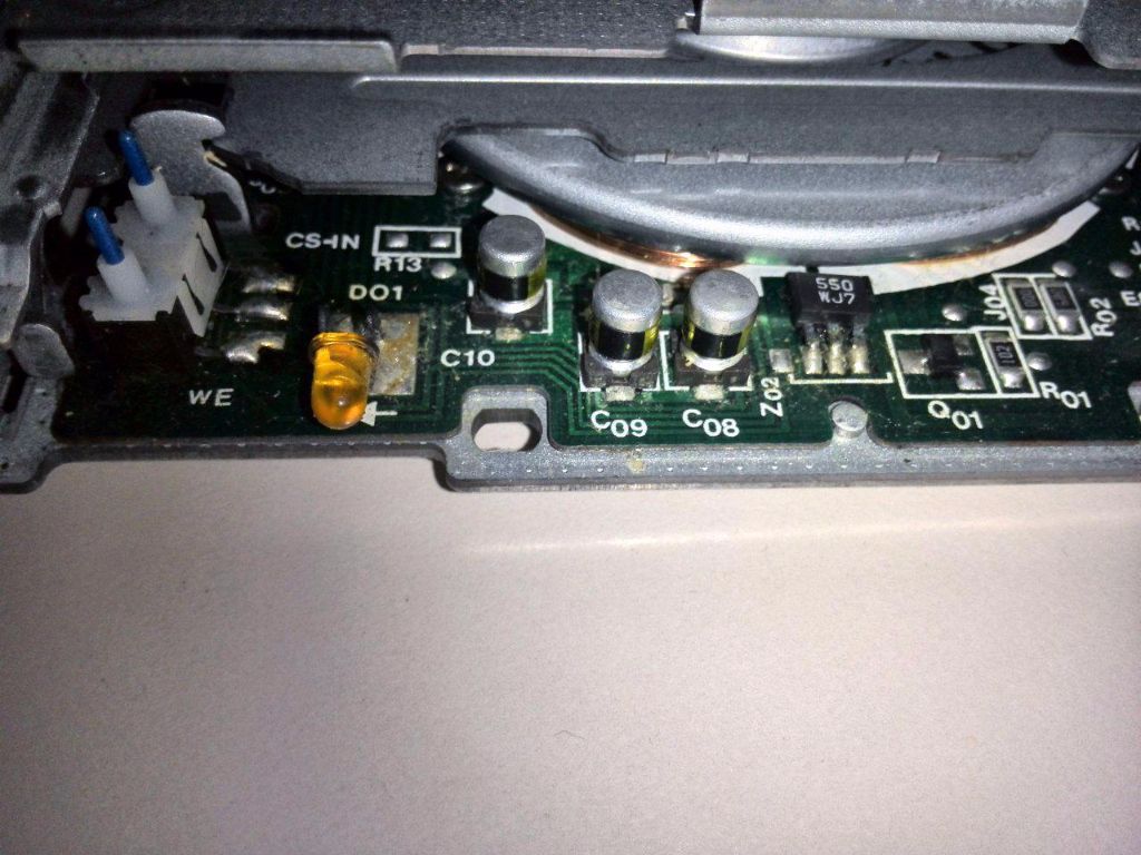 | 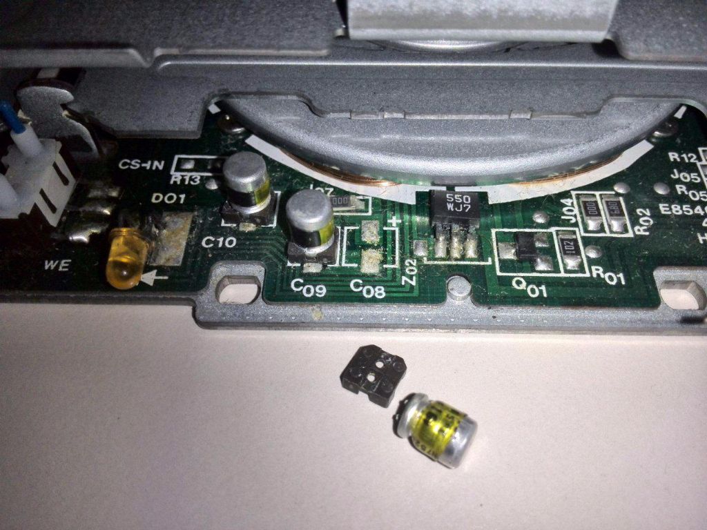 |
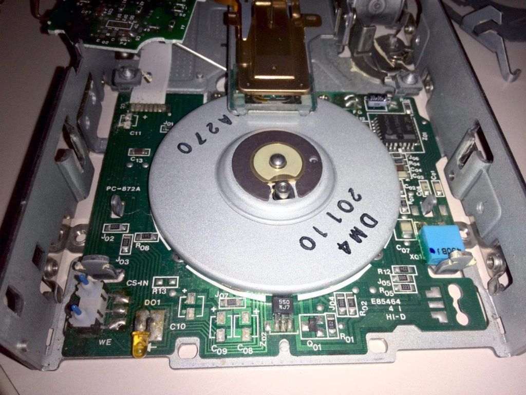
| Here is the partially disassembled EPSON SMD-400 floppy drive—you can already see the leaking electrolytic capacitors here. | Looking at the removed electrolytic capacitor, you can already see that it has leaked and is beginning to destroy the circuit board. |
Solder in new electrolytic capacitors – pay attention to polarity.
Each contact must then be wetted with fresh solder. Standard 10 µF electrolytic capacitors are suitable replacements; these should be installed lying flat (see image). Important: The negative side of the capacitor—marked with a stripe on the casing—must be connected to the negative terminal indicated on the motor control board; the unmarked side is positive. Be sure not to reverse the polarity—otherwise, you’ll end up with a little Chinese firecracker inside the drive 🙂
|
|
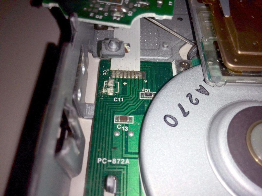
| Here you can see the entire motor control board with the electrolytic capacitors removed. What a—to use a Bavarian expression—"mess"! All the solder pads and the surrounding contacts need to be cleaned with "Kontakt WL" to neutralize the electrolyte; then, all the contacts must be desoldered and re-tinned. | Here you can see the neat "drive hack" using brand-new, oversized 105°C low-ESR electrolytic capacitors mounted horizontally. This allows you to use standard capacitors instead of SMD types. Thanks to the capacitors' thickness, there are no clearance issues—the lower drive carriage doesn't rub against them. Just make sure the polarity matches the markings on the circuit board; otherwise, a capacitor installed with the wrong polarity could burst, and we certainly don't want that! 🙂 |
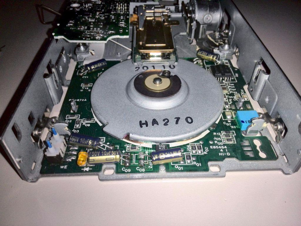
In the picture, you can see the completed "drive hack" featuring new, intentionally oversized 105°C low-ESR electrolytic capacitors mounted horizontally. This eliminates the need for SMD capacitors, allowing the use of standard leaded ones. The height of the capacitors poses no issue, as the lower drive carriage does not rub against this area. The only crucial thing is ensuring the polarity matches the markings on the circuit board exactly—otherwise, a capacitor installed with the wrong polarity could burst, and we certainly don't want that! 🙂
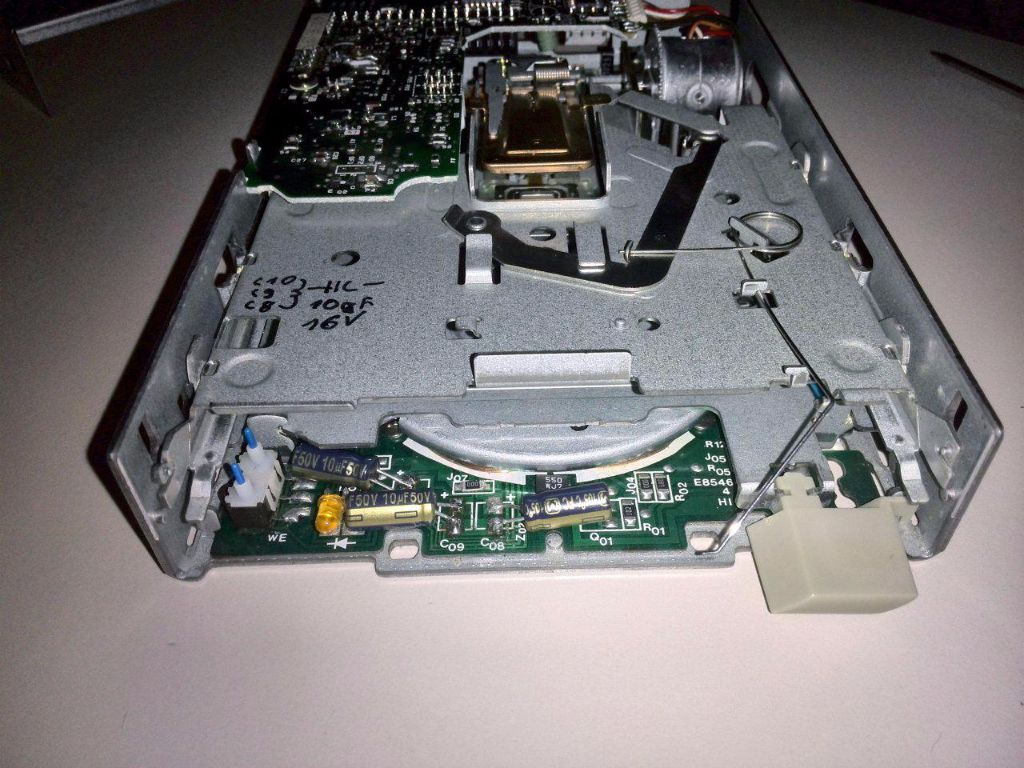
The height of the electrolytic capacitors fits perfectly under the carriage, so nothing rubs.
Assembly: Be careful with the springs.
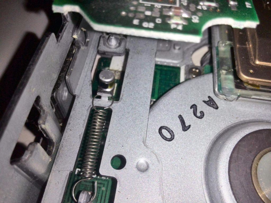
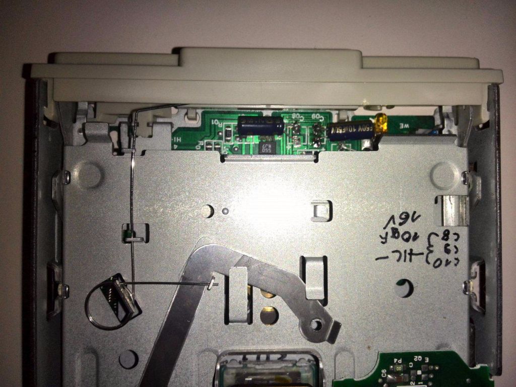
For this retro repair, I’m assuming you have experience dismantling disk drives. The ejection mechanism springs, in particular, can drive an inexperienced person to tear their hair out 🙂 The two lower springs for the carriage aren't a problem, but the spring for the upper carriage—located at the back left—can drive you absolutely mad if you don't know the right trick.
Conclusion
The drive is now repaired and should function perfectly again. The contact switch for disk detection and write protection might cause some trouble in the future, though—more on that soon in a separate post.
![Atari SFP004 [Atari ST]](https://www.jungsi.de/blog/wp-content/uploads/Atari-SFP004-Oberseite.jpg)
![SMM804 [Atari]](https://www.jungsi.de/blog/wp-content/uploads/SMM804_2.jpg)
![WiModem232 OLED [Atari ST u.a.]](https://www.jungsi.de/blog/wp-content/uploads/WiModem-232-verbunden.png)
Danke für deinen Beitrag. Konnte mein Laufwerk wiederbeleben. Bei mir war der Kontaktschalter kaputt vorne, der die Diskette erkennt.
Hallo Gerhard,
beim Durchsuchen in diversen ATARI-Foren zum Thema:
Reparatur von „alten“ Floppy-Laufwerken, bin ich
auf Deine Seite „Jungsis Corner“ aufmerksam geworden.
Da gibt es auch den erfolgreichen Bericht:
„Epson SMD-400 Wiederbelebung [Atari ST]“
vom 01.12.2015 von „Darius“
Nach ca. 25 Jahren habe ich meinen ATARI STE vom Dach-
boden hervor geholt und aufgebaut.
Beim Klick auf das interne DD-LW „Epson SMD-380“ geht
die gelebe LED zwar an. Lesezugriff durch den Steppmotor
erfolgt aber leider nicht 🙁 . . . LW ist gereinigt
Nach dem lesen des Berichtes SMD-400 Wiederbelebung
habe ich nun die Hoffnung, dass ich das SMD-380 mit
etwas „Lötgeschick“ auch wieder ans Laufen bekomme.
Folgende Kondi´s habe ich auf dem SMD-380 gefunden:
1. direkt neben 5V Anschluss sitzt:
1 dicker, brauer Kondensator; rel. gut aus-/einzulöten
Bezeichnung: C01
Farbe: braun
Beschriftung oben 99 B3
Beschriftung seite 56uF 16V
Durchmesser: 6mm
Höhe: 7,5mm
2. hinter der Kunststoffblende (Disk-Einschub)
sitzen 3 kleine schwarze Kondi´s (ähnlich SMD-400)
alle 3 Kondi´s sind umgeklappt und an der Platine angeklebt
Die Kondi-Beinchen können nicht durchgesteckt werden
Die Löt-Anschlussstellen sind abgeflacht und 90° abgebogen
Bezeichnung: C1 + C2 + C3 [(M) 88 CE 85°C]
Farbe: schwarz
Beschriftung oben — — (keine)
Beschriftung seite 22uF 10V
Durchmesser: 4mm
Höhe: 6,5mm
Feststellung:
C2 + C3 sind gut zu erreichen
C1 wird etwas fummelig, müsste aber auch gehen
Die Pertinax-Platine im Bereich Einschub, ist unten aus Metall
(geklebt !?)
Alle 3 Kondi´s haben die gleiche Bezeichnung
C1 – (M) 88 10 V 22uF CE 86°C
C2 – (M) 88 10 V 22uF CE 86°C
C3 – (M) 88 10 V 22uF CE 86°C
Nun zu meinen Fragen:
– sind außer den 4 Kondi´s noch weitere Kondi´s „versteckt“ ?
– könnten ggf. noch weitere Bauteil/e defekt sein ?
– wenn ja, welche ?
– welche Tipps zum Reparaturversuch kannst Du mir noch geben ?
P.S.
Da die Kondi´s relativ günstig bei z.B. reichelt beschafft werden
können, möchte ich den Reparaturversuch gerne durchführen.
Vorab schon mal herzlichen Dank für Deine Unterstützung
und viele Grüße
Thomas
Hallo Thomas, vielen Dank für Deine Frage. Leider kann ich Dir deine Fragen nicht beantworten. Das war einer der wenigen Artikel, die ich nicht selbst geschrieben habe. Mit dem Autor habe ich keinen Kontakt mehr und meine Kenntnisse in diesen Details sind mehr als gering. Außerdem habe ich diese Basteleien auf Grund meiner schlechten Augen aufgegeben. Tut mir leid.
Viele Grüße
Jungsi
Hallo! Ganz dumme Frage: Ich will ein Check-up an meinem Laufwerk machen, aber trotzdem kann ich die Gehäuse(diese Metalschale) nicht entfernen. Ich weiß nicht wie man das macht. Würden Sie mir bitte ein bisschen erkären? Danke schön
Stefan
Hallo. Es gibt keine dummen Fragen. Leider kann ich hier nicht behilflich sein. Das ist der einzige Artikel im ganzen Blog, den ich bisher nicht selbst geschrieben hatte.
Leider hab ich selbst keines dieser Laufwerke und mit dem Autor des Artikels habe ich leider keinen Kontakt mehr.
Viele Grüße
Gerhard
Danke für die Antwort! Ich habe den Weg gefunden. Es gab eine Schraube, die alles hielt.
Und auch mir hat diese Anleitung sehr geholfen, in meinem XT waren 2 Stück dieser SMD 400 Laufwerke verbaut, beide mit 26 Pin Stecker über die auch der Strom geführt wurde. Austausch also nicht ohne weiteres möglich… 5 Minuten, 5 Kondensatoren später liefen die Laufwerke wieder… Gebaut wie ein Panzer bis auf die billigen 3Cent Kondensatoren an denen wieder gesparrt wurde…